
Protected: Reference
There is no excerpt because this is a protected post.
There is no excerpt because this is a protected post.
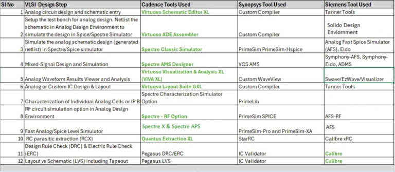
Top EDA Tools for Analog & Mixed Signal IC Design In the intricate world of integrated circuit (IC) design, selecting the right electronic design automation (EDA) tool is pivotal for success, especially in the realms of analog and mixed-signal designs. These EDA tools, encompassing analog synthesis, simulations with a SPICE simulator, and complex analog modeling,…
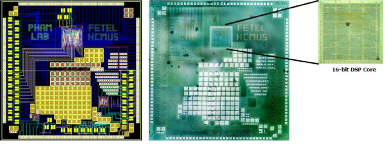
Analog IC Design Flow to Tapeout – The fabrication of a prototype IC chip is a highly costly and time-consuming process, requiring significant financial investment and an extended timeline ranging, at least, from several months to even a year for completion. Tapeout: refers to the final stage of the design process, just before sending it…
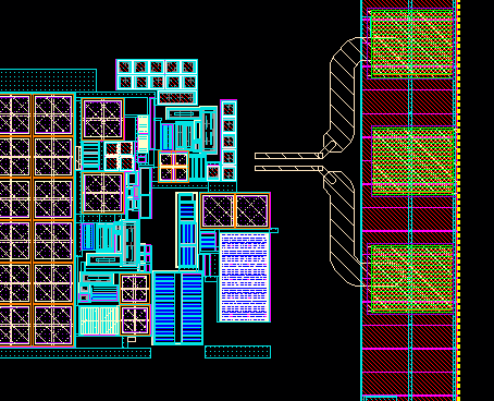
VLSI Physical Design Flow The chip design includes different types of processing steps to finish the entire flow. For anyone, who just started his career in VLSI physical design domain has to understand all the steps of the VLSI physical design flow. Each and every step of the VLSI physical design flow has a dedicated…
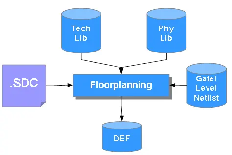
Design Exchange Format – DEF stands for Design Exchange Format. DEF file is a standardized data file that represents the physical layout of design. This file is given as an input to the EDA tool. We can generate this file at every stage of design flow. To send placement information from one stage to another…
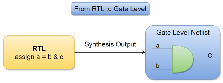
Netlist File – What is Netlist in VLSI Design Flow Netlist or Netlist File, a crucial representation in VLSI design, outlines the connectivity of an electronic circuit in textual format. Netlist contains the electrical connections between the components on the circuit board and is usually held in a textual format. In an electronic circuit netlist…
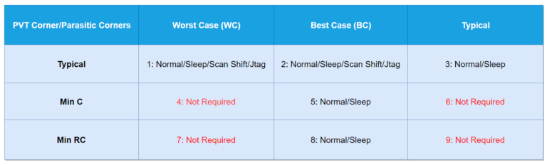
MMMC Configuration & Multi Mode Multi Corner File What is MMMC ? MMMC means Multi Mode Multi Corner. This file is used to analyze the design in different Modes and Corners. Because the chip after manufacture have to work properly for different temperatures, voltage, and while manufacturing there might be some process variations or in…
In Physical Design Flow (Some call backend of the IC Design Flow) there are many types of input files are used starting from RTL to the final tapeout (Sending GDS2 file) to the semiconductor IC manufacturing fabs. Let us list out and try to understand each of the file in a detailed way. Type of Input…
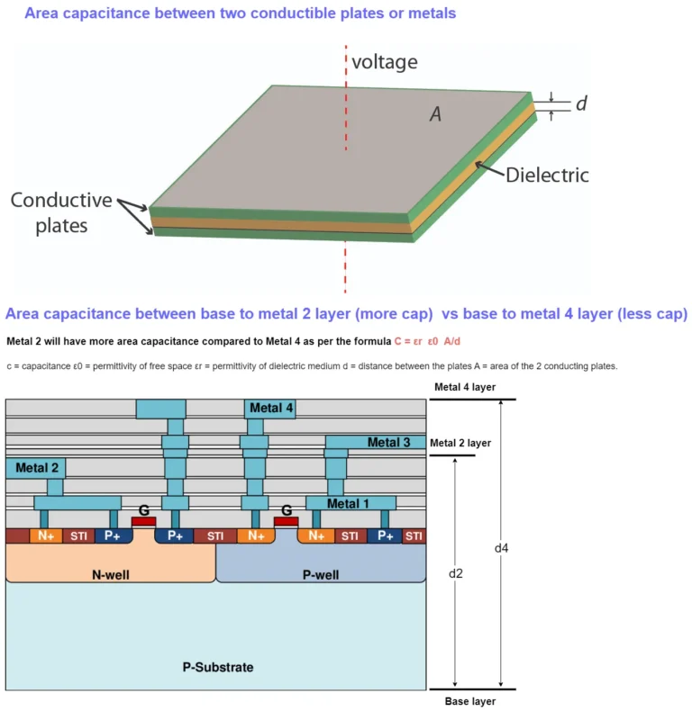
Device Basics – Passive Elements/Devices In this section we are going to read some basics of electrical engineering and semiconductor physics before jump into Physical Design or layout of the IC design. First thing you need to know is Physical Design is not a rocket science. Anyone who have basic knowledge of electrical/electronics engineering can…
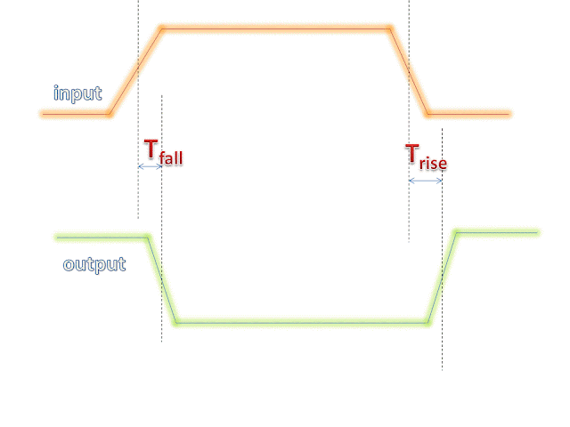
What is Liberty Format ? Lib file is a short form of Liberty Timing file. Liberty syntax is followed to write a .lib file. LIB file is an ASCII representation of timing and power parameter associated with cells inside the standard cell library of a particular technology node. Liberty format is an industry standard format…
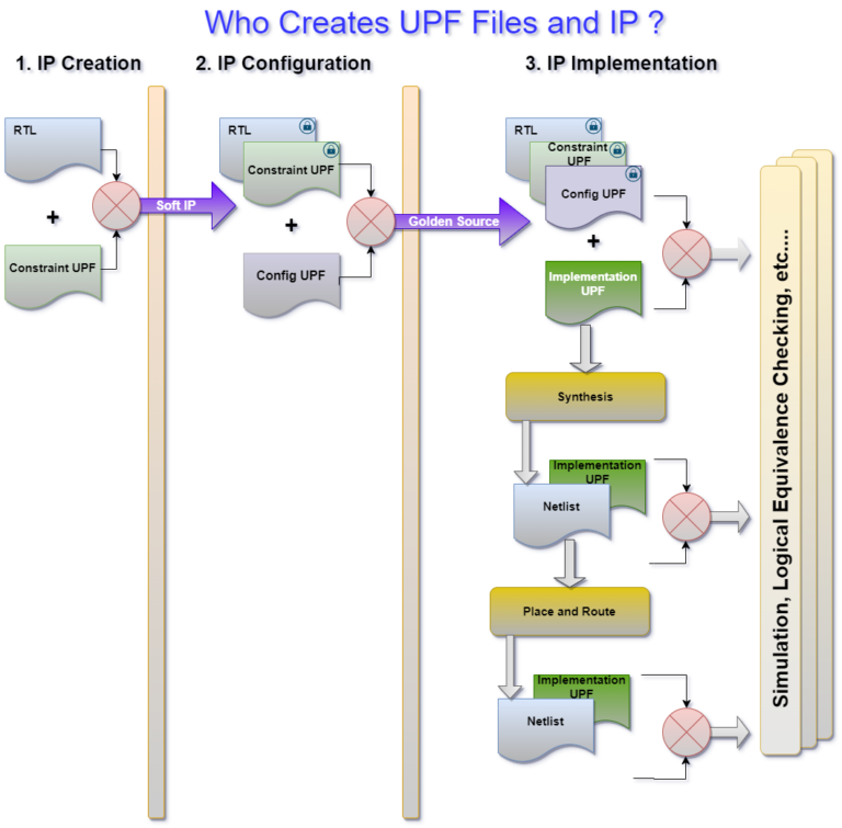
UPF ( Unified Power Format) in the Logic Synthesis Flow of VLSI Design & Verification UPF is an acronym for Unified Power Format which is an IEEE standard for specifying power intent. In this article let’s understand the UPF files and tool flow and also we will learn about writing an UPF for a given…
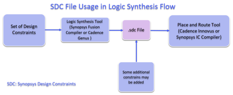
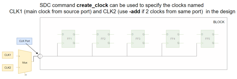
SDC (Synopsys Design Constraints) File in the Logic Synthesis Flow of VLSI Design What is SDC & SDC Introduction? SDC or the Synopsys Design Constraints (SDC) is a common format for constraining the design which is supported by almost all Synthesis including Cadence Synthesis tool Genus and Siemens Synthesis Catapult, and other tools/steps such as PnR….