VLSI Designers Choice of EDA Tools in Each Step of ASIC Design Flow
VLSI Design Steps & Designers Choice of EDA Tools
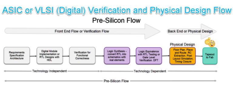
VLSI Design Steps and Designers Choice of EDA Tools in Each Step of ASIC Design Flow – VLSI Verification & Physical Design Flow or Pre-Silicon Flow of Digital VLSI/ASIC
These are the top EDA tools or the Top Preferences of the VLSI Designers in Each Step of the ASIC Design Flow while designing the complex VLSI Chips
RTL Design & Simulation
RTL (Register Transfer Level) design engineer converts the specification into an RTL code using the HDL (Hardware Description Language) generally either in Verilog, SystemVerilog, or VHDL. After writing the RTL code, the RTL designer simulates the code in an RTL Simulator such as Synopsys’s VCS, Cadence’s Xcelium and Siemens QuestaSim to check the design’s functionality. They create various test benches at this stage to verify the design’s functionality under different conditions. Sometimes, the SystemC is also used, mainly to simulate system level Design, Architecture Description and verification of system level. System Verilog’s new features such as assertions and other important features used for design as well as for verification.
VLSI Designers Choice to Simulate RTL:
VCS from Synopsys is often considered the best for this step due to its high performance, capacity, and low total time to results. It provides fast simulation for both single-core and multi-core configurations, making it ideal for complex designs.
Competitor EDA tools in the market to consider:
Xcelium Digital Simulator from Cadence and Questasim Digital simulator from Siemens
Logic Synthesis
In this step, the design team converts a high-level description of the design (RTL Code) into an optimized gate-level representation using a specific standard cell library and incorporating defined design constraints. The output of this step is a gate-level netlist of a particular standard cell library.
VLSI Designers Choice for Synthesis:
 Fusion Compiler from Synopsys(earlier Design Compiler, Read Note), is often used because it provides superior quality of results and convergent design closure. It integrates RTL-to-GDSII tools into a unified flow, enabling faster convergence with better Quality of Results.
Competitor EDA tools in the market to consider:
Genus from Cadence and Catapult from Siemens
Note – About Fusion Compiler:
Fusion Compiler is the result of the Synopsys’s bold initiative to build a new architecture from the ground up around a single, unified data-model that fuses synthesis, place and route (P&R) and signoff technologies in an unprecedented way to maximize PPA. Fusion Compiler, enabling 20 percent higher quality-of-results and 2X faster time-to-results. Fusion Compiler is the industry’s only RTL-to-GDSII product architected with a single, scalable data model, best-in-class optimization engines, and an analysis backbone based on the industry’s golden signoff tools.
Logic Equivalence Check (LEC)
This is done to make sure that there are not logical changes occurred during the synthesis. It ensures that the synthesized design is logically equivalent to the RTL design. Logic equivalence checking(LEC) looks at the combinatorial structure of the design to determine if the structure of two alternative implementations will exhibit the same behavior. If operations such as retiming are applied to a design, the structure of the design will no long map between the two representations (RTL vs Synthesized cells/circuits/gates).
Sequence equivalency checking (SEC) takes timing into account and examines the equivalency of two design representations over multiple clock cycles.
VLSI Designers Choice for LEC:
 Conformal from Cadence is preferred because it provides comprehensive and high-performance equivalence checking. It ensures that the RTL and gate-level netlists are functionally identical, reducing the risk of functional errors.
Competitor EDA tools in the market to consider:
Formality from Synopsys and FormalPro from Siemens
Static Timing Analysis (STA)
Static Timing Analysis (STA) is a method used in digital circuits to validate the timing performance of a design. It checks all possible paths for timing violations by breaking down a design into timing paths, calculating the signal propagation delay along each path, and checking for violations of timing constraints.
VLSI Designers Choice for Static Timing Analysis:
 PrimeTime from Synopsys is often used because it provides comprehensive analysis and signoff of timing, signal integrity, and power. It offers fast, accurate, and comprehensive timing and signal integrity (SI) analysis, enabling designers to achieve timing closure faster.
Competitor EDA tools in the market to consider:
Tempus from Cadence and I didn’t see any tool from Siemens so far.
DFT (Design For Testability) Insertion
This is done in this stage to verify the chip after fabrication is done. It involves adding additional circuitry i.e., scan cells to the design to make it easier to test and to increase the coverage of the testing process.
VLSI Designers Choice for DFT:
 TestMax DFT & TestMax ATPG from Synopsys is a comprehensive solution for implementing various DFT methodologies such as SCAN chain insertion, test point insertion, compression insertion, boundary scan insertion, and core wrapping. It is useful for multi-level compressor-decompressor architecture implementation, which can be helpful in optimizing test data volume and test time. One of the key reasons for its popularity is its ability to seamlessly integrate with other Synopsys tools, providing a complete flow from design to test. This allows for a smooth transition from design to test preparation, reducing the overall design cycle
Competitor EDA tools in the market to consider:
Modus ATPG from Cadence and Tessent FastScan from Siemens.
Place and Route (PnR)
The goal of Place and Route stage is to place all the standard cells, Macros and I/O pads with minimal area, with minimal delay and Route them together in such a way that there is no DRC (Design Rule Check) error. The final output of this stage is the layout of design in the form of GDSII file.
VLSI Designers Choice for Place and Route:
 Innovus from Cadence is often chosen because it provides a fast, power-efficient integrated physical design solution. It uses a massively parallel architecture to provide scalability and speed, enabling designers to handle large, complex designs.
Competitor EDA tools in the market to consider:
IC Compiler (Now ICC2) from Synopsys and Aprisa from Siemens
RC Extraction
After completing the Place and Route (PnR) step, the design extracts into an RC (resistance-capacitance) network. Post-layout simulation and analysis, including Static Timing Analysis (STA), then use this RC network to ensure the design meets its timing, power, and performance goals.
VLSI Designers Choice for RC Extraction:
 Quantus RC Extraction by Cadence is popular because it provides best-in-class accuracy and performance. It ensures accurate parasitic extraction, which is critical for achieving timing and signal integrity goals.
Competitor EDA tools in the market to consider:
StarRC from Synopsys and Calibre xRC from Siemens
Physical Verification
This is the final step before the design is sent for manufacturing. It involves checking the design for manufacturability, reliability, and electrical issues. It ensures that the design meets all the foundry-specific layout rules.
Physical verification involves three steps, namely:
1. Design Rule Check (DRC): DRC determines if a chip layout satisfies a number of rules as defined by the semiconductor manufacturer
2. Electrical Rule Check (ERC): ERC verifies the correctness of power and ground connections, and that signal transition times (slew), capacitive loads and fanouts are appropriately bounded
VLSI Designers Choice for DRC & ERC:
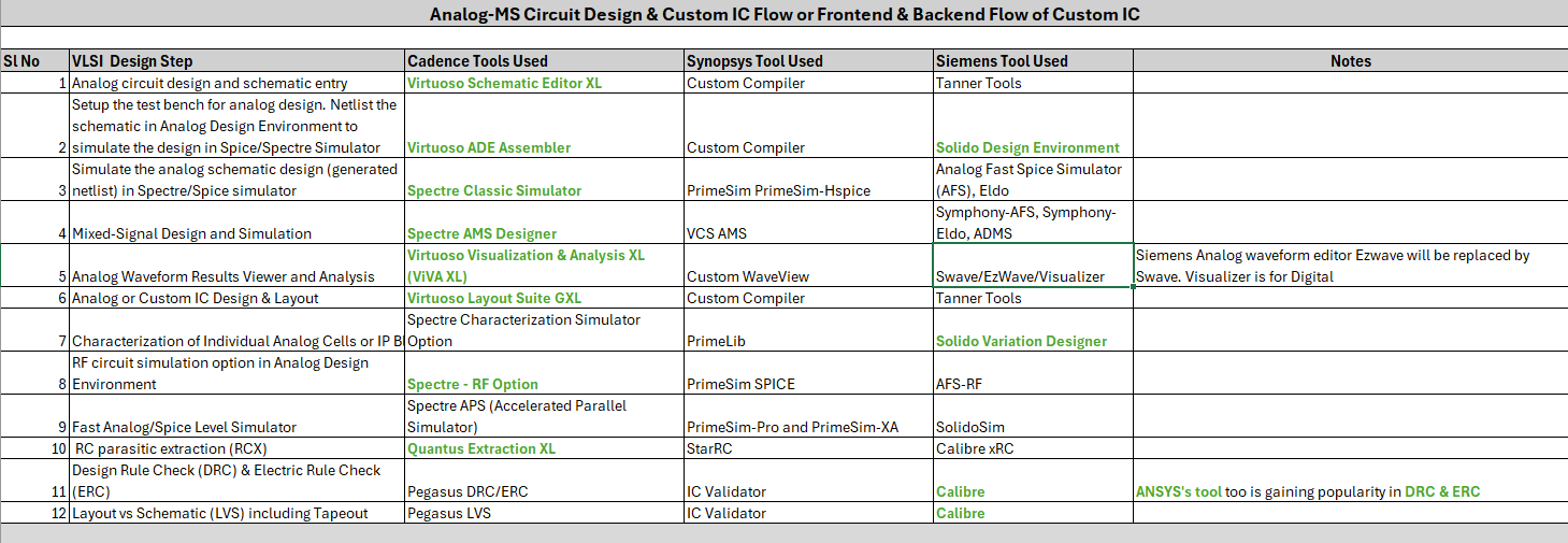
 Ansys Tools is a popular choice. Ansys is an emerging provider of simulation software that engineers use to design and analyze complex systems. Ansys supports ASIC design flow. Tools for power, signal, thermal integrity, ESD, and more. Handles complex Multiphysics problems in ASICs. Variability in on-chip scenarios managed effectively. RedHawk Fusion: ANSYS RedHawk-driven EM/IR analysis and optimization within place-and-route is gaining popularity.
3. Layout Versus Schematic (LVS):
LVS verifies the functionality of the design. The design derives a netlist from the layout and compares it with the original netlist from logic synthesis or circuit design.
VLSI Designers Choice for LVS:
 Calibre from Siemens is often considered one of the best tools for overall Physical Verification. It excels in handling complex designs and large data volumes, making it suitable for advanced process nodes due to its high performance. Another reason is its wide acceptance in the industry. Many foundries provide rule decks for Calibre, ensuring that the checks performed are accurate and up-to-date with the latest process requirements.
Competitor EDA tools in the market to consider:
IC Validator from Synopsys and Pegasus from Cadence
Tape-out
In the final step of the design process, designers hand off the design data to the foundry for manufacturing. This step involves generating the final data files required by the foundry to manufacture the ASIC.
 VLSI Designers Choice during the Tapeout:
Calibre from Siemens is a popular choice. In the tape-out process, designers use Calibre to perform final checks on the design before sending it for manufacturing. Calibre checks for any violations of manufacturing process rules. If violations are found, designers must fix them before the design can be taped out. Calibre’s comprehensive checking capabilities make it an invaluable tool in this process.
Competitor EDA tools in the market to consider:
IC Validator from Synopsys and Pegasus from Cadence
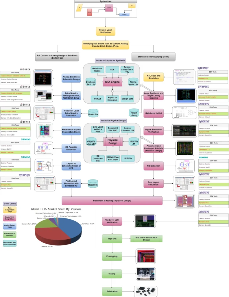
EDA Tool Map between Cadence Synopsys and Siemens
Pre-Silicon Flow of Analog and Digital ASIC Designs
Note: EDA Tool name that are in green colored text are preferred choice of EDA tools for the VLSI Designers.
Conclusion
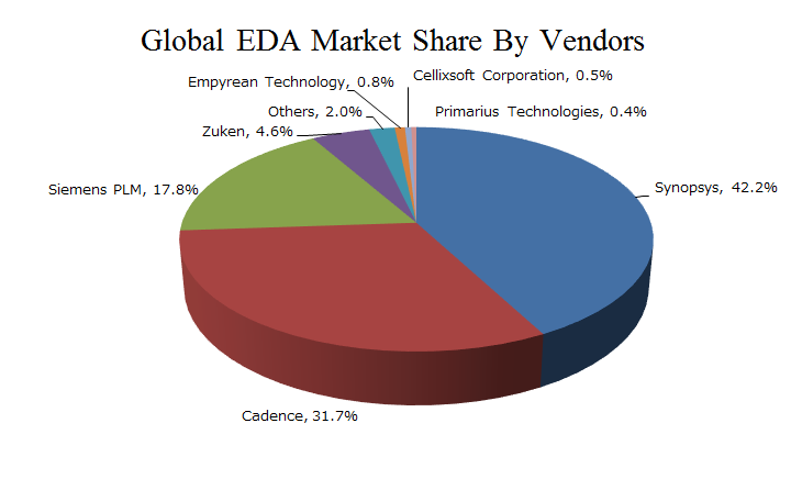
The ASIC design flow outlined predominantly relies on EDA (Electronic Design Automation) tools from industry leaders Synopsys and Cadence.
VLSI Designers Favor:
1. Synopsys’s VCS, Fusion Compiler, PrimeTime, TestMax DFT tools for RTL design, Logic Synthesis, STA, DFT insertion are preferred choices for VLSI designers..
2. Cadence’s Innovus and Quantus RC Extraction tools excel in place and route as well as post-layout extraction. Cadence’s Conformal excel during Logic Equivalence Check.
3. Siemens’s Calibre enjoys widespread adoption in physical verification including LVS, & Tapeout.
4. Ansys’s RedHawk tool enjoys widespread adoption in DRC/ERC & EM/IR analysis.
SystemC in Verification and Key Differences in HDL’s
Using SystemC for RTL/C/C++ Co-simulation
SystemC is an extension language to standard C/C++ with the use of class libraries., this makes it a natural language for System-level design, modeling and verification.
SystemC is cycle-accurate. The main components include:
1. Signals. These connect two or more modules together, providing a means for transferring and communicating data in a system
2. Ports. The entry way (input, output, or inout) to a module
3. Modules. These are similar to an ENTITY and sensitivity list in VHDL
4. Main Program (sc_main)
Instantiating an RTL design Unit with SystemC
Instantiating an RTL module within SystemC is quite straightforward. All you need to do is to write a SystemC foreign module for the RTL, which can be later used as a native SystemC class. The below snippet illustrate a sample VHDL entity and its SystemC counterpart:
Sample VHDL design unit:
entity counter is
port(
clk : in std_logic;
reset: in std_logic;
count: out std_logic_vector(7 downto 0)
);
end;
architecture rtl of counter is
…
end rtl;
The SystemC module counterpart:
class counter : public sc_foreign_module {
public:
sc_in clk;
sc_in reset;
sc_out<sc_lv<8> > count;
counter(sc_module_name nm) : sc_foreign_module(nm, “work.counter”),
clk(“clk”),
reset(“reset”),
count(“count”) {
}
};
You can either hand write the SystemC module or automatically generate it using the scgenmod utility.
Writing BFMs with SystemC:
Because SystemC is cycle-accurate, writing BFMs using SystemC is straightforward.
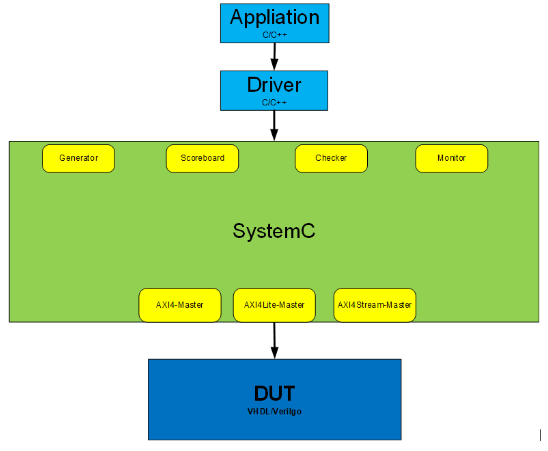
The SystemC for AXI4-Lite read can be implemented something similar to below using Vivado tools:
Write your own Xil_io.c in SystemC, which calls the SystemC BFMs
u32 Xil_In32(UINTPTR Addr) {
u32 data;
…………..
…………..
}
Using SystemC for RTL – Block Diagram
Software Requirements:
1. Software tool requirements for this reference design include:
2. Vivado Design Suite
3. ModelSim/QuestaSim
4. Precompiled Vivado libraries for ModelSim/QuestaSim
Example project setup:
1. Launch Vivado, create a project targeting any device/board.
2. In Vivado Tools, from the Create and Package New IP wizard, select to Create a new AXI4 peripheral, and create an AXI4 peripheral using the default template.
3. Create the SystemC foreign module wrapper using scgenmod
4. Write your own Xil_io.c in SystemC, which calls the SystemC BFMs written above.
5. After compiling and linking everything together, launch simulation using vsim.
Difference between the different RTL languages
Verilog:
– descibes pure logic behaviour (states: 0, 1, X, Z)
– simulation requires a pure logic simulator (e.g. Xcelium/VCS/QuestaSim)
– can be used for digital synthesis
– is a IEEE standard
Verilog-A:
– describes analog circuit behaviour – modelling with voltages and currents
– simulated requires an analog simulator (e.g. Spectre/Hspice/FineSim/AFS/Eldo/Spice)
– cannot be used for digital synthesis
– not an IEEE standard – it belongs to company Accellera
Verilog-AMS:
– a combination of Verilog and Verilog-A – allows logic and real-number-modelling (e.g. wreal built-in resolution functions)
– simulation requires both digital and analog simulators (e.g. Xcelium and Spectre) in vendor specific tool-environment (Virtuoso-AMS)
– cannot be used for digital synthesis
– not an IEEE standard – it belongs to company Accellera
SystemVerilog:
– an extension to Verilog – allows logic and real-number-modelling (e.g. no built-in – but option for customized – resolution functions)
– simulation requires digital simulator (e.g. Xcelium)
– can be used for digital synthesis
– is an IEEE standard
SystemC and SystemVerilog Key Differences
SystemC:
1) based on C++. So SystemC main benefit is leverage from C++ language.
2) is used for system design
3) is useful in system verification
4) is useful to model a system in transaction level
5) useful for hardware/software co-design and co-verification
6) A subset of C++
7) Implementation simulator (C++ compiler) is freely available
8) Architectural Design and Verification
9) system C – transaction level modelling
Transaction level model is just for verification or simulation, it just is a data control model. And most of the designers like to use SystemVerilog, because SystemC is a co-simulation, it need two tools and two languages to run.
SystemVerilog is superset of Verilog, so it just one tools and one language. SystemC mainly for system level Design, Architecture Description and verification of system level. System Verilog’s new features such as assertions and other important features used for design as well as for verification. SystemC is built into a lot of the simulators now, including Modelsim and Aldec. This means no PLI, and no slowdown in runtime.
SystemVerilog:
1) is used for Hardware design
2) is used when we are going to verify block-level designs
3) is a superset of traditional Verilog
4) can be used at RTL and gete level descriptions
5) Adds many features to support verification (e.g. Assertions)
6) adds many features from VHDL that were missing in Verilog
7) RTL & Gate level Design and Verification
8) SystemVerilog – signal level modelling
Here are some open questions and answers:
Q1. Requires Verilog-AMS code an analog simulator, or can Verilog-AMS code also be simulated in a pure logic simulator (e.g. Xcelium) ?
Ans: Verilog-AMS code can be run on a logic simulator if the code is limited to just the digital domain and no “analog” blocks or “electrical” signals. At that point, it may be called Verilog-AMS, but it is really just the Verilog subset.
Q2. When I want to write portable models (behavioral models that can be reused in other simulators from Mentor, Synopsys, Siemens etc.), can I do this for both Verilog-AMS and SystemVerilog ?
Ans: Theoretically, if you stick to the LRM, the models should run on other simulators. However, not all vendors have implemented all aspects of the LRM (especially in Verilog-AMS).
Q3. When I want to write portable models for a pure digital simulator with real-number-modelling, I assume SystemVerilog would be the correct choice ?
Ans: SystemVerilog has the most comprehensive set of constructs for RNM. Verilog-AMS does have ‘wreal’ construct but it is not supported equally by all vendors and does not provide as much capability as SystemVerilog or VHDL.
SystemVerilog and Verilog-AMS are not considered the same thing. You probably had a problem that could be solved with either VAMS code or SV code, but they would be two different solutions. Xcelium can run Verilog, SystemVerilog, Verilog-AMS, VHDL, and VHDL-AMS, but it doesn’t mean those are all the same thing. They are different languages that are all supported by a single simulator.
What is RTL and Difference between RTL and Behavioral Code
RTL is an acronym for Register Transfer Level. This implies that your Verilog code describes how data is transformed as it is passed from register to register. The transforming of the data is performed by the combinational logic that exists between the registers.
Behavioral Code: By definition it defines the behavior of a digital component. It does not give information how it will be implemented into actual HW (synthesis). It will not give information how registers and gates will be implemented to perform required operation. It is more like writing an algorithm or FSM in C. Behavioral code is higher-level and usually can’t be synthesized. Constructs like loops, delays, and “initial” statements are behavioral.
RTL: RTL code is lower-level and is intended to be synthesized. It defines a circuit as a combination of interconnected registers and the operations performed on signals between those registers. It is more precise form of a digital component. It gives information, how code will be implemented as actual HW (after synthesis). Also it gives information how data will be transferred between registers and gates.





This article offers invaluable insights into the essential EDA tools used throughout the ASIC design flow. The detailed breakdown of each step is incredibly helpful for both novice and experienced VLSI designers looking to enhance their workflow. Thank you for sharing such informative content that bridges the gap between theory and practical application.