Different Type of Input Files Required for Physical Design Flow
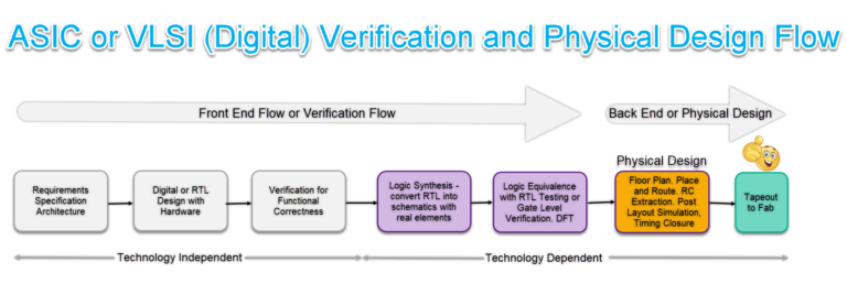
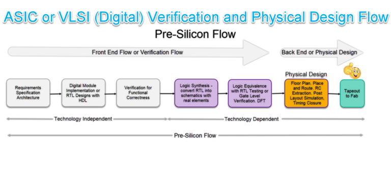
In Physical Design Flow (Some call backend of the IC Design Flow) there are many types of input files are used starting from RTL to the final tapeout (Sending GDS2 file) to the semiconductor IC manufacturing fabs. Let us list out and try to understand each of the file in a detailed way.
Type of Input Files Required for Physical Designs.
Different types of Input Files are listed below:
- Register Transfer Level (RTL)
- Timing Library (.lib)
- SDC
- Library Exchange Format (LEF)
- Multi Mode Multi Corner
- Netlist
- Design Exchange Format (DEF)
- RC Coefficient
- Standard Parasitic Exchange Format (SPEF)
- Unified Power Format (UPF)
- GDS & OASIS
Register Transfer Level (RTL) File
- RTL stands for Register Transfer Level.
- Its primary usage is to facilitate data transfer from one register to another.
- Usually, RTL code is developed by using HDL (Hardware Description Language) like VHDL or Verilog.
- In other words, building a digital design harnessing sequential and combinational circuits in HDL, such as Verilog or VHDL, which can describe hardware and logical behavior.
- RTL code is independent of technology node, that means same code can be used without any changes for different technology nodes like 45nm, 28nm, 22nm, 7nm, 5nm, 3nm etc..
- RTL code is given as an input to the synthesis tool, then tool implements the design and generates “Netlist” as an output which is also a Verilog format.
Examples of RTL Code for D Flip Flop in Various HDL
In Verilog Language:
Verilog Code for Rising Edge D Flip Flop:
// Verilog code for D Flip Flop
// Verilog code for rising edge D flip flop
module RisingEdge_DFlipFlop(D,clk,Q);
input D; // Data input
input clk; // clock input
output Q; // output Q
always @(posedge clk)
begin
 Q <= D;
end

endmodule
In SystemVerilog Language:
SystemVerilog Code for Rising Edge D Flip Flop:
// SystemVerilog code for D Flip Flop
// SystemVerilog code for rising edge D flip flop
module RisingEdge_DFlipFlop (
input  wire D  , // Data Input
input  wire clk   , // Clock Input
output reg  Q       // Q output
);

 always @(posedge clk)
Q <= D;
end

endmodule
In VHDL Language:
VHDL code for Rising Edge D Flip Flop:
-- FPGA projects using VHDL/ VHDL
-- fpga4student.com
-- VHDL code for D Flip FLop
-- VHDL code for rising edge D flip flop
Library IEEE;
USE IEEE.Std_logic_1164.all;

entity RisingEdge_DFlipFlop is
   port(
      Q : out std_logic;
      Clk :in std_logic;
      D :in  std_logic
   );
end RisingEdge_DFlipFlop;
architecture Behavioral of RisingEdge_DFlipFlop is

begin
 process(Clk)
 begin
    if(rising_edge(Clk)) then
   Q <= D;
    end if;
 end process;

end Behavioral;
Timing Library (.lib) File
Timing library (.lib) is also known as liberty file. It can be readable through human because of it is implemented in ASCII format. These timing libraries generated by the library vendors or foundries. A typical timing library will have information of standard cells like timing, area and power. Timing can be implemented by using timing models under different operating conditions (PVT).
There are mainly two types of timing models are present to model the timing libraries:
- NLDM (Non Linear Delay Model)
- CCS (Composite Current Source)
NLDM and CCS are used to calculate the delay of standard cells. So, cell delays are depends on applying different input transitions and output load capacitances. These input transition and output load capacitances are includes into liberty file in the form of look-up tables.
CCS is accurate compared to NLDM. NLDM is modeled by using voltage source and CCS is modeled by using current source. NLDM modeled libraries run times are faster compared to CCS modeled libraries. And also NLDM modeled libraries are smaller in file size but CCS modeled libraries are very larger in size.
Notes:
Delay of cells depends on input transition and output load under different operating conditions based on timing models.
The following templates reflects only mandatory content. Depending on the technology and requirements some extra feature would be added to the timing library.
Timing libraries will have 3 parts:
- Header
- LUT (Look-up Table)
- Cell definition
Header
- It contains some information which is common for all the standard cells
- The information is like library name, units, operating conditions and date of creation
Template of Timing Library
library (<library_name>);→ timing library name

delay_model :table_lookup;→ it define the delay model of this library


 /* unit attributes */

time_unit :<time_unit>;→ units of time (usually in nano seconds, ns)

voltage_unit :<voltage_unit>;→ units of voltage

current_unit :<current_unit>;→ units of current (usually in milliampere, mA)

pulling_resistance_unit :<resistance_unit>;→ units of resistance (usually in kilo ohm, kohm)

leakage_power_unit :<power_unit>;→ units of power (usually in nano watts, nW)

capacitive_load_unit (<value>, capacitace_unit);→ units of capacitance (usually in pico farad, pf)


 /*slew and threshold values in percentage to calculate delay*/

slew_upper_threshold_pct_rise : <value>;→ slew upper threshold value of rise percentage

slew_lower_threshold_pct_rise : <value>;→ slew lower threshold value of rise percentage

slew_upper_threshold_pct_fall : <value>;→ slew upper threshold value of fall percentage

slew_lower_threshold_pct_fall : <value>;→ slew lower threshold value of fall percentage

input_threshold_pct_rise : <value>;→ rise signal input threshold percentage

input_threshold_pct_fall : <value>;→ fall signal input threshold percentage

output_threshold_pct_rise : <value>;→ rise signal output threshold percentage

output_threshold_pct_fall : <value>;→ fall signal output threshold percentage

nom_process : <value>;→ nominal process (usually 1 is the value)

nom_voltage : <value>;→ nominal voltage (ex: 1.32V, 0.5V, 1V, 0.8V, etc..,)

nom_temperature : <value>;→ nominal temperature (ex: 125⁰C, -40⁰C, 0⁰C, etc..,)


 /*cells in this library works under these operating conditions*/

operating_conditions( <operating_condition_name> );→ this library cells works under this operating conditions

process : <value>;

voltage : <value>;

temperature : <value>;

power_rail( RAIL_VDD, <value>);

power_rail( RAIL_VSS, 0 );

}
Example of Header Section in .lib Library File
/*
 delay model :       typ
 check model :       typ
 power model :       typ
 capacitance model : typ
 other model :       typ
*/
library(foo) {

  delay_model : table_lookup or LUT;
  in_place_swap_mode : match_footprint;

  /* unit attributes */
  time_unit : "1ns";
  voltage_unit : "1V";
  current_unit : "1mA";
  pulling_resistance_unit : "1kohm";
  leakage_power_unit : "1nW";
  capacitive_load_unit (1,pf);

  slew_upper_threshold_pct_rise : 80;
  slew_lower_threshold_pct_rise : 20;
  slew_upper_threshold_pct_fall : 80;
  slew_lower_threshold_pct_fall : 20;
  input_threshold_pct_rise : 30;

  input_threshold_pct_fall : 70;
  output_threshold_pct_rise : 70;
  output_threshold_pct_fall : 30;
  nom_process : 1;
  nom_voltage : 5;
  nom_temperature : 25;
  operating_conditions ( typical ) {
     process : 1;
     voltage : 5;
     temperature : 25;
  }
  default_operating_conditions : typical;
LUT (Look-Up Table)
- LUT means look-up table. It can be find just below of header section
- It’s the prototype of delay, hold, recovery and removal and power
- Look-up table values are subjected to change inside pin definitions.
Template of Look-Up-Table
lu_table_template(<label_of_table>) {

variable_1 :<variable_name>;

variable_2 :<variable_name>;

index_1 (“<variable_1 data points>”);

index_2 (“<variable_2 data points>”);

}
Example of Look-Up Table
lu_table_template(delay_template_5x5) {
    variable_1 : input_net_transition;
    variable_2 : total_output_net_capacitance;
    index_1 ("1000.0, 1001.0, 1002.0, 1003.0, 1004.0");
    index_2 ("1000.0, 1001.0, 1002.0, 1003.0, 1004.0");
  }
  power_lut_template(energy_template_5x5) {
    variable_1 : input_transition_time;
    variable_2 : total_output_net_capacitance;
    index_1 ("1000.0, 1001.0, 1002.0, 1003.0, 1004.0");
    index_2 ("1000.0, 1001.0, 1002.0, 1003.0, 1004.0");
  }
  lu_table_template(hold_template_5x3) {
    variable_1 : constrained_pin_transition;
    variable_2 : related_pin_transition;
    index_1 ("1000.0, 1001.0, 1002.0, 1003.0, 1004.0");
    index_2 ("1000.0, 1001.0, 1002.0");
  }
  power_lut_template(passive_energy_template_5x1) {
    variable_1 : input_transition_time;
    index_1 ("1000.0, 1001.0, 1002.0, 1003.0, 1004.0");
  }
  lu_table_template(recovery_template_5x3) {
    variable_1 : constrained_pin_transition;
    variable_2 : related_pin_transition;
    index_1 ("1000.0, 1001.0, 1002.0, 1003.0, 1004.0");
    index_2 ("1000.0, 1001.0, 1002.0");
  }
  lu_table_template(removal_template_5x3) {
    variable_1 : constrained_pin_transition;
    variable_2 : related_pin_transition;
    index_1 ("1000.0, 1001.0, 1002.0, 1003.0, 1004.0");
    index_2 ("1000.0, 1001.0, 1002.0");
  }
  lu_table_template(setup_template_5x3) {
    variable_1 : constrained_pin_transition;
    variable_2 : related_pin_transition;
    index_1 ("1000.0, 1001.0, 1002.0, 1003.0, 1004.0");
    index_2 ("1000.0, 1001.0, 1002.0");
  }
  lu_table_template(width_template_5x1) {
    variable_1 : related_pin_transition;
    index_1 ("1000.0, 1001.0, 1002.0, 1003.0, 1004.0");
  }
Cell Definition
- Cell definition section contains cell information like cell name, cell area, leakage power, rail connection for both VDD and VSS
- This section includes pin definition also. Pin definition contains information like pin direction (input, output or inout), signal level, pin capacitance, rise capacitance, fall capacitance
- If the pin is output pin then function of the cell (logic of cell)
- State tables are available for every sequential element
Template of Cell Definition in Library
cell (<cell_name>) {→ cell name

area :<cell_area>;→ cell area

cell_leakage_power :<leakage_power_value>;→ leakage power

rail_connection( VDD, RAIL_VDD );→ VDD for cell rail connection

rail_connection( VSS, RAIL_VSS );→ VSS for cell rail connection

ff () or latch () → state table for sequential element

pin(<pin_name>) {→ pin name

direction :<pin_direction>;→ pin direction input, output orinout

input_signal_level : RAIL_VDD;→ pin input signal level only if input pin

output_signal_level : RAIL_VDD;→ pin output signal level only if output pin

capacitance : <value>;→ pin capacitance

rise_capacitance : <value>;→ pin rise capacitance

fall_capacitance : <value>;→ pin fall capacitance

function : “<cell_logic>”;→ cell logic only if the pin is output

timing() {→ timing of output pin only if output pin

related_pin : “<pin_name>”;→ related pin name

timing_sense :<pin_unateness>;→ unateness of pin (positive, negative or non unateness)

cell_rise(delay_template_7x7) {→ timing definition by using look-up tables

index_1 (“<7 values>”);

index_2 (“<7 values>”);

values ( <set of values upto 7×7>)

}
Example of Cell Definition of INVX1
/* -------------- *
 * Design : INVX1 *
 * -------------- */
cell (INVX1) {
  cell_footprint : inv;
  area : 3;
  cell_leakage_power : 0.0341756;
  pin(A)  {
    direction : input;
    capacitance : 0.0160164;
    rise_capacitance : 0.0160164;
    fall_capacitance : 0.0159693;
    rise_capacitance_range ( 0.0160164, 0.0160164) ;
    fall_capacitance_range ( 0.0159693, 0.0159693) ;
  }
  pin(Y)  {
    direction : output;
    capacitance : 0;
    rise_capacitance : 0;
    fall_capacitance : 0;
    rise_capacitance_range ( 0, 0) ;
    fall_capacitance_range ( 0, 0) ;
    max_capacitance : 0.402017;
    function : "(!A)";
    timing() {
      related_pin : "A";
      timing_sense : negative_unate;
      cell_rise(delay_template_5x5) {
        index_1 ("0.06, 0.18, 0.42, 0.6, 1.2");
        index_2 ("0.025, 0.05, 0.1, 0.3, 0.6");
        values ( \
          "0.147583, 0.217035, 0.355377, 0.907001, 1.73349", \
          "0.224219, 0.291274, 0.428044, 0.977438, 1.80305", \
          "0.365232, 0.445422, 0.582152, 1.12428, 1.94149", \
          "0.46186, 0.55044, 0.700788, 1.23784, 2.0566", \
          "0.75585, 0.872701, 1.05674, 1.62712, 2.42849");
      }
      rise_transition(delay_template_5x5) {
        index_1 ("0.06, 0.18, 0.42, 0.6, 1.2");
        index_2 ("0.025, 0.05, 0.1, 0.3, 0.6");
        values ( \
          "0.09712, 0.164583, 0.299488, 0.839163, 1.64852", \
          "0.117867, 0.173862, 0.30016, 0.839221, 1.64879", \
          "0.174063, 0.229801, 0.335188, 0.839268, 1.64864", \
          "0.212233, 0.270216, 0.376329, 0.849921, 1.64867", \
          "0.322205, 0.398154, 0.51726, 0.945327, 1.66712");
      }
      cell_fall(delay_template_5x5) {
        index_1 ("0.06, 0.18, 0.42, 0.6, 1.2");
        index_2 ("0.025, 0.05, 0.1, 0.3, 0.6");
        values ( \
          "0.166552, 0.247549, 0.408769, 1.04944, 2.00953", \
          "0.234229, 0.313057, 0.472061, 1.11143, 2.07233", \
          "0.366262, 0.455096, 0.610195, 1.24173, 2.19801", \
          "0.456648, 0.553252, 0.718877, 1.34254, 2.29658", \
          "0.732451, 0.855462, 1.05488, 1.6961, 2.63335");
      }
      fall_transition(delay_template_5x5) {
        index_1 ("0.06, 0.18, 0.42, 0.6, 1.2");
        index_2 ("0.025, 0.05, 0.1, 0.3, 0.6");
        values ( \
          "0.103393, 0.176429, 0.322563, 0.906541, 1.78269", \
          "0.119174, 0.182264, 0.32239, 0.906789, 1.78367", \
          "0.176141, 0.235883, 0.351112, 0.906842, 1.78324", \
          "0.215097, 0.277743, 0.390555, 0.911993, 1.78282", \
          "0.333403, 0.409933, 0.534675, 0.99795, 1.79573");
      }
    }
    internal_power() {
      related_pin : "A";
      rise_power(energy_template_5x5) {
        index_1 ("0.06, 0.18, 0.42, 0.6, 1.2");
        index_2 ("0.025, 0.05, 0.1, 0.3, 0.6");
        values ( \
          "0.389002, 0.393869, 0.398499, 0.402791, 0.40412", \
          "0.442829, 0.430625, 0.423648, 0.413675, 0.40862", \
          "0.617376, 0.577985, 0.535474, 0.47171, 0.448634", \
          "0.768465, 0.717378, 0.652041, 0.547541, 0.493993", \
          "1.29533, 1.2207, 1.10425, 0.86946, 0.7254");
      }
      fall_power(energy_template_5x5) {
        index_1 ("0.06, 0.18, 0.42, 0.6, 1.2");
        index_2 ("0.025, 0.05, 0.1, 0.3, 0.6");
        values ( \
          "0.011845, 0.00625, 0.001276, 0.005383, 0.006277", \
          "0.022784, 0.017685, 0.013616, 0.008902, 0.007861", \
          "0.173984, 0.138231, 0.101902, 0.054497, 0.035459", \
          "0.311874, 0.256871, 0.196965, 0.106444, 0.069818", \
          "0.81705, 0.723427, 0.595846, 0.372799, 0.246518");
      }
    }
  }
}
State Table Example for Flip Flop
ff (DS0000,DS0001) {
    next_state : "D";
    clocked_on : "(!(!CLK))";
    clear : "(!CLR)";
  }
Note: Every Sequential element has a state table
Click this link to download the full example of the Timing Library File (.lib)
Video – Mastering Static Timing Analysis (STA) with Liberty Timing Library (.lib)
Synopsys Design Constraints (SDC) File
- SDC stands for Synopsys Design Constraints. It was developed by Synopsys Company.
- It is an open source file with “.sdc” as an extension.
- SDC commands are developed based on TCL (Tool Command Language) which is supported by almost all EDA tools.
- By using SDC, timing, area and power constraints are provides to the tools like synthesis, PnR and STA.
- It contains design timing information like clock definitions, generated clocks, virtual clocks, clock transitions, input port delays, output port delays, wireload model, timing exceptions and DRVs, etc.…
Commands in the SDC Constraints
1. Timing constraints
create_clock
create_generated_clock
set_clock_groups
set_clock_latency
set_clock_transition
set_clock_uncertainty
set_clock_sense
set_propagated_clock
set_input_delay
set_output_delay
set_clock_gating_check
set_ideal_latency
set_ideal_network
set_ideal_transistion
set_max_time_borrow
set_resistance
set_timing_derate
set_data_check
group_path
set_drive
set_load
set_input_transition
set_fanout_load

2. Area and power constraints:
set_max_area
create_voltage_area
set_level_shifter_threshold
set_max_dynamic_power
set_level_shifter_strategy
set_max_leakage_power

3. Design rule constraints:
set_max_capacitance
set_min_capacitance
set_max_transition
set_max_fanout

4. Interface constraints:
set_drive
set_driving_cell
set_input_transition
set_load
set_fanout_load
set_port_fanout_number
set_input_delay
set_output_delay

5. Specific modes and configurations constraints:
set_case_analysis
set_load_dc
set_logic_zero
set_logic_one

6. Timing exceptions:
set_false_path
set_multi_cycle_path
set_disable_timing
set_max_delay*
set_min_delay*

7. Miscellaneous commands:
set_wire_load_model
set_wire_load_mode
set_wire_load_selection_group
set_wire_load_min_block_size
set_units set_operating_conditions
sdc_version
Some of the important SDC constraints are listed below with their definitions:
sdc_version: The version of the SDC is specified through this command.
Example: set sdc_version 2.0
set_units: This command specifies the units of various parameters like capacitance, resistance, voltage, time, current and power.
Syntax: set_units-capacitance cap_unit -resistance res_unit -time time_unit -voltage voltage_unit -current current_unit -power power_unit
Example: set_units -time ns -resistance Kohm -capacitance pF -voltage V -current mA
create_clock
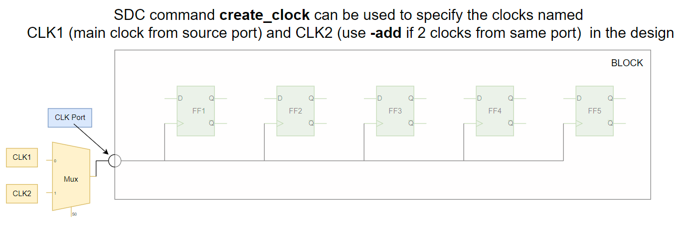
The command to specify the clock in the design is create_clock.
Syntax: create_clock [-name clock_name] [clock_sources] [-period value] [-waveform edge_list] [-add] [-comment].
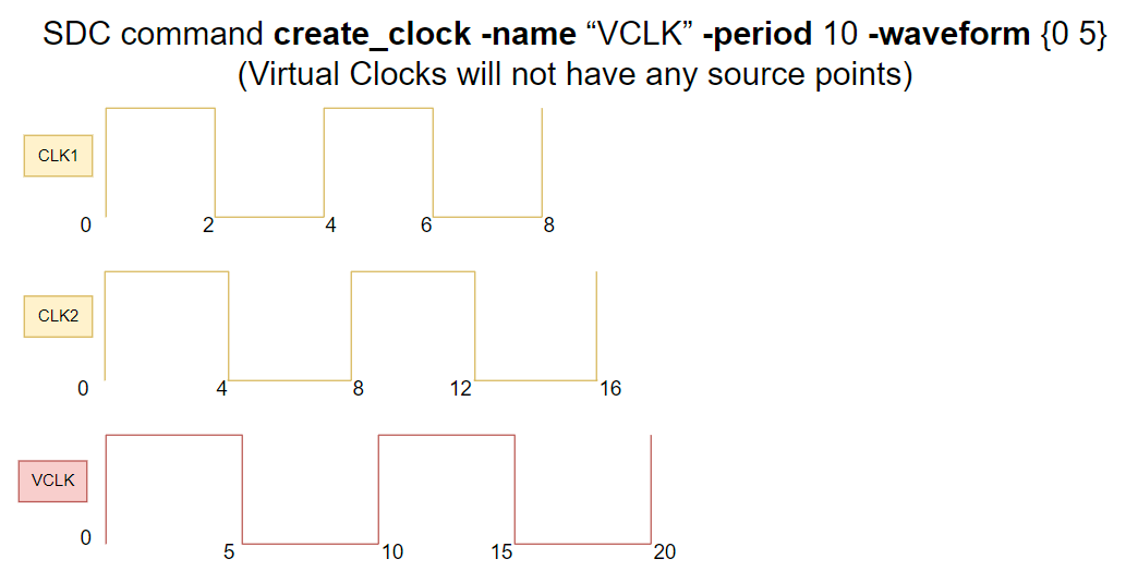
Example1: create_clock -name “CLK1” -period 4 -waveform {0 2} [get_portsclk] (main clock comes from a particular port i.e.., source point)
Example2: create_clock -name “CLK2” -period 8 -waveform {0 4} [get_portsclk] -add (if 2 clocks are coming from same port then -add has to mention in the command).
Following figure shows an example:
Example3: create_clock -name “VCLK” -period 10 -waveform {0 5} (Virtual Clocks will not have any source points)
Create_generated_clock
The command to specify the generated clocks in the design is “set_generated_clock”. These generated clocks are derived from main clocks in the design by using frequency dividers or frequency multipliers.
Syntax: create_generated_clock [source_objects] -source clock_source_pin [ -master_clockmaster_clock_name] [ -name generated_clock_name] [ -edges edge_list] [ -divide_by factor] [ -multiply_by factor] [ -invert ] [ -edge_shiftshift_list] [ -duty_cycle percent] [ -combinational ] [ -add ] [ -comment comment_string]
Example: create_clock -period 4 -name CLK [get_ports CLK] create_generated_clock -name GCLK -source [get_port CLK] -divide_by 2 [get_pins FF1/Q]
set_clock_transition
This command specifies the transition times of a clock or set of clocks.
Syntax: set_clock_transition [-rise ] [-fall ] [-max ] [-min ] transition_timeclock_list
Examples:
set_clock_transition -rise 0.14 -min [get_clocks CLK] #Rise transition for min operating condition.
set_clock_transition -rise 0.21 -max [get_clocks CLK] #Rise transition for max operating condition.
set_clock_transition -fall 0.2 [get_clocks CLK] #Fall transition for min and max conditions.
set_clock_transition 0.11 [all_clocks] #same transition value reflects for all rise, fall, min and max.
set_clock_latency
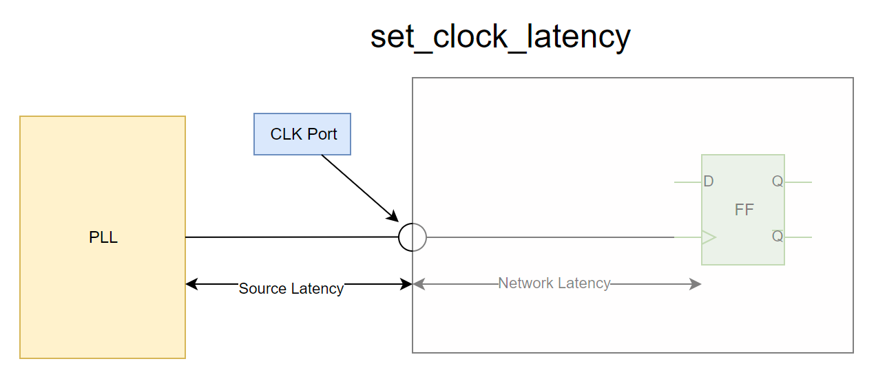
Latency means the amount of time taken by the clock to reach from clock port to clock pin of sequential element. There are two latency components, source latency and network latency. To specify source latency “-source” switch has to mention in the command.
Syntax: set_clock_latency- rise ] [- fall ] [- min ] [- max ] [- source ] [- late ] [- early ] [- clock clock_list] delay object_list
Examples:
set_clock_latency -source -early 0.3 [get_clocks CLK] #Source latency for shortest path.
set_clock_latency -source -late 0.8 [get_clocks CLK] #Source latency for longest path.
set_clock_latency 0.5 [get_clocks CLK] #Network latency
set_clock_uncertainty
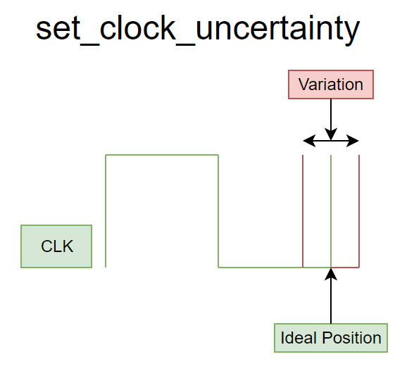
For ideal clocks, clock edges are arrives time. But for real clocks, there may a variation in arrival of clock edges. For example, consider a clock with 1ns time period, for ideal clock rise edge come at 0ns and fall edge comes at 0.5ns and again rise edge comes at 1ns. For real clock, there may be variation like rise edge come at 0.02ns and fall edge comes at 0.54ns and again rise edge comes at 1ns. This happens because of clock skew, crosstalk and OCV. This will affect the timing, to model this variation clock uncertainty using.
Uncertainty classified into two types: Intraclock uncertainty and Interclock uncertainty.
Intraclock uncertainty: Clock skew can be between different points of the same clock
Interclock uncertainty: Clock skew can be between different clocks.
Syntax: set_clock_uncertainty [-from | -rise_from | -fall_fromfrom_clock] [-to |-rise_to | -fall_toto_clock] [-setup ] [-hold ] [-rise ] [-fall ] [object_list] Uncertainty_value
Examples:
set_clock _uncertainty 0 . 5 [get_clocks CLK] #Intraclock uncertainty for both setup and hold
set_clock_uncertainty -setup 0 . 5 [get_clocks CLK] #Intraclock uncertainty for setup
set_clock_uncertainty -hold 0 . 2 [get_clocks CLK] #Intraclock uncertainty for hold
set_clock_uncertainty -from CLK1 -to CLK2 -setup 0.6 #Interclock uncertainty for setup
set_clock_uncertainty -from CLK1 -to CLK2 -hold 0.9 #Interclock uncertainty for hold
set_input_delay
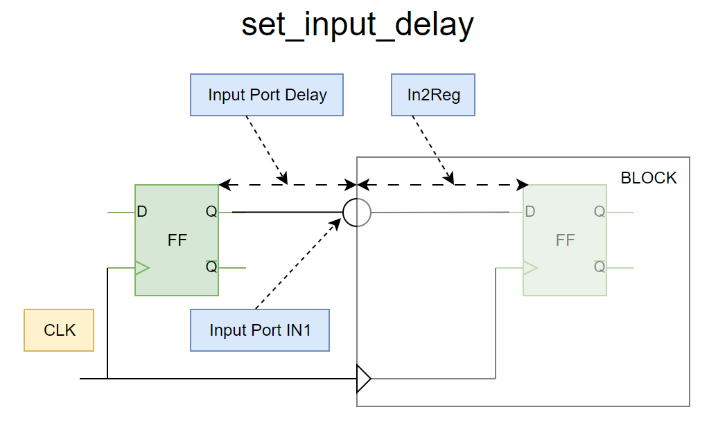
This command specifies the data arrival timings relative to the clock indicated by the “-clock” option at the selected input port. If input delay not specified then tool considers that input delay is zero and uses entire clock to model the in2Reg timing path.
Syntax: set_input_delay [ -clock clock_name] [ -clock_ fall ] [ -level_sensitive ] [ -rise ] [ -fall ] [ -max ] [ -min ] [ -add_delay ] [ -network_latency_included ] [ -source_latency_included ] delay_valueport_pin_list
Examples:
set_input_delay -clock CLK 1.5 [get_ports IN1] #input port IN1 delay
set_input_delay -clock CLK1 2.0 [all_inputs] #same delay for all input ports
set_output_delay
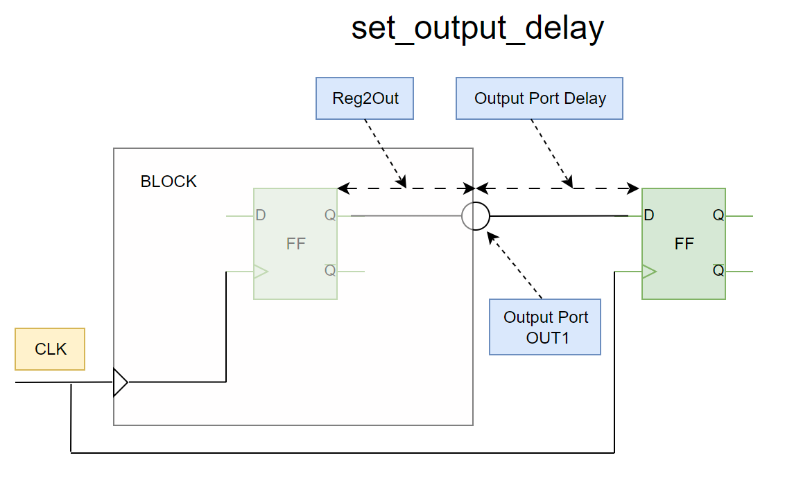
This command specifies the data required timings relative to the clock indicated by the “-clock” option at the selected output port. If input delay not specified then tool considers that input delay is zero and uses entire clock to model the Reg2Out timing path.
Syntax: set_output_delay [ -clock clock_name] [ -clock_ fall ] [ -level_sensitive ] [ -rise ] [ -fall ] [ -max ] [ -min ] [ -add_delay ] [ -network_latency_included ] [ -source_latency_included ] delay_valueport_pin_list
Examples:
set_output_delay-clock CLK 2.5 [get_ports OUT1] #output port OUT1 delay
set_input_delay -clock CLK1 2.2 [all_outputs] #same delay for all output ports
set_false_path
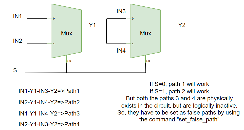
The paths which are physically existing in the design but logically inactive in the functionality in the chip, those paths are considered as false path. For false paths, there is no need to calculate timing. Those kinds of paths are specified by using set_false_path command.
Syntax: set_false_path [- setup ] [- hold ] [- rise ] [- fall ] [- from from_list] [- to to_list] [- through through_list] [- rise _from rise_from_list][- rise_torise_to_list] [- rise_throughrise_through_list] [- fall_fromfall_from_list] [- fall_tofall_to_list] [- fall_throughfall_through_list] [- comment comment_string]
Example: set_false_path -from {FF1} -to {FF2} set_false_path -from [get_clocks {my_clk}] -to [get_clocks {test_clk}]
set_multicycle_path
By default, all paths are single cycle paths means the data launched at current active clock edge should receive at immediate next clock edge. But, depending ondesigners requirements some of the path require more than one clock cycle to capture data reliably (to meet setup and hold timings). So, those path which require more than one clock cycle are considered as multicycle paths and specified as multicycle paths using “set_multicycle_path”.
Syntax: set_multicycle_path [ -setup ] [ -hold ] [ -rise ] [ -fall ] [ -start ] [ -end ] [ -from from_list] [ -to to_list] [ -through through_list] [ -rise_fromrise_from_list] [ -rise_torise_to_list] [ -rise_throughrise_through_list] [ -fall_fromfall_from_list] [ -fall_tofall_to_list] [ -fall_throughfall_through_list] path_multiplier [ -comment comment_string]
Example: set_multicycle_path 2 -from ff1/Q -to ff2/D
set_max_delay
This command specifies the maximum delay on timing path. For example, a required maximum delay is 6ns then it can be specified by using set_max_delay.
Syntax: set_max_delay [ -rise ] [ -fall ] [ -from from_list] [ -to to_list] [ -through through_list] [ -rise_fromrise_from_list] [ -rise_torise_to_list] [ -rise_throughrise_through_list] [ -fall_fromfall_from_list] [ -fall_tofall_to_list] [ -fall_throughfall_through_list] delay_value [ -comment comment_string]
Example: set_max_delay -from [get_ports IN1] -to [get_ports OUT1] 6.0
set_min_delay
This command specifies the minimum delay on timing path. For example, a required minimum delay is 3ns then it can be specified by using set_min_delay.
Syntax: set_min_delay [ -rise ] [ -fall ] [ -from from_list] [ -to to_list] [ -through through_list] [ -rise_fromrise_from_list] [ -rise_torise_to_list] [ -rise_throughrise_through_list] [ -fall_fromfall_from_list] [ -fall_tofall_to_list] [ -fall_throughfall_through_list] delay_value [ -comment comment_string]
Example: set_min_delay -from ff1/Q -to ff2/D 3.0
set_max_fanout
This command specifies the maximum fanout for a pin or port in the design.
Syntax: set_max_fanoutfanout_valueobject_list
Example: set_max_fanout 16 [current_design] #All pins fanout will be 16
set_max_transition
It is the maximum time taken to change logic from 0 to 1 or 1 to 0.
Syntax: set_max_transitiontransition_value [-data_path] [-clock_path] [-rise] [-fall]object_list
Example: set_max_transition 0.2 UCLKDIV0/QN
set_max_capacitance
This command specifies the maximum capacitance for an output pin of a cell.
Syntax: set_max_capacitance value object_list
Example: set_max_capacitance 0.2 [current_design]
Library Exchange Format (LEF) File
LEF stands for Library Exchange Format. It is also termed as physical library, because this file contains physical abstract information of Layers and standard cells / macros. It is implemented in ASCII format, so it can be readable by human. These physical libraries generated by the library vendors or foundries.
Physical libraries are two types:
- Technology LEF
- Standard Cell/Macro LEF
Technology LEF
Technology LEF will have information of library version, units, manufacturing grid and layers information.
Library version: This field show the library version.
Example: VERSION 5.1
Unit definition: This field contains information of units like database, time, capacitance and resistance information. Values specified in the file will be multiplied with units.
Example: CAPACITANCE PICOFARADS 1 ;
Manufacturing grid: The minimum metal length that can be manufactured is called manufacturing grid.
Example: MANUFACTURINGGRID 0.005 ;
Site: Site is the minimum standard cell area that can be manufacturable.
Example:
SITE CoreSite
CLASS CORE ;
SIZE 0.2 BY 1.71 ;
END CoreSite
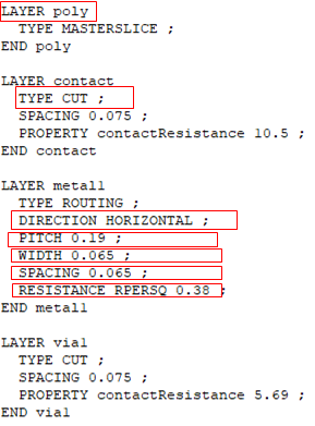
Layer information: This field contains information like Layer name, Type, Direction, Pitch, Width, Area, Spacing and thickness, etc.…,
Template:
Layer name (like poly, contact, via1, metal1 etc.)
Layer type ( like routing, masterslice, cut etc.)
Preferred direction (like horizontal or vertical)
Pitch
Minimum width
Spacing
Sheet resistance
Here’s an example poly, contact, via and metal1 section of the technology LEF file:
Standard Cell/Macro LEF
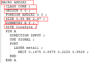
This LEF contains abstract view of each and every standard cell. The cell LEF contains basic information like Cell name, Class, Origin, Size, Symmetry, Pin information(pin name, direction, shape, etc.…)
Click here to Know Cell Abstract Generation using Cadence Virtuoso
Visit Silicon Synergy to know More
Explore our IC Design Courses in Analog IC Design, Digital Design & Verification

